Electric Cooler Go Kart
Growing up, I always wanted a gas powered go kart, but lack of money and anywhere practical to ride it kept me from my dreams. Now with a job and some money, I still have no where practical to ride it.

Why a cooler? I just thought it was kind of a funny novelty idea that could be used at a tailgate or summer party. The form factor posed some interesting challenges that made this a fun project.

Finished Picture!*
* Not totally finished.
Specifications:
Revolt RV-120 Pro sensored brushless DC motor would for 64kV. The shaft has a custom 3/4" (19mm) end with keyway to accept many common sprockets.
Kelly KLS7230S sinusoidal brushless motor controller rated for 300 amp bursts and 120 amp continuous operation at up to 90 volts.
Two Turnigy Multistar 6s 16 AH batteries wired in series (44.4 volts, 16AH, 710Wh).

My first Idea was to keep all of the gear outside of the cooler and keep the cooler intact. I wanted to get a little better at 3D modeling, so once I had a good idea of the parts I wanted, I used Fusion 360 to sketch up key components to make sure everything would fit the way I wanted
I ended up with a design where the electronic components would be hidden in the cooler.

I printed some drawings of the frame and motor mount.
The frame is made out of 1" OD DOM steel tube with a 0.083" wall thickness. The space I worked at did not have any pipe or tubing benders so I notched the tubing, bent it to shape and welded up the notches. This tube was bent into one of the corners.

That same tube after bending.

All welded up. This was my first time welding so I made good use out of the grinder and flap disc sander.

All cleaned up.

The shop also didn't have a tubing notcher so I used a cut off wheel and bench grinder to shape tubing for proper fit up. In hindsight, I should have just purchased a tubing notcher and maybe a bender. It would have saved a lot of time.

Frame coming together

Making the motor mount. I had to make sure the holes were smooth as wires needed to pass through them.
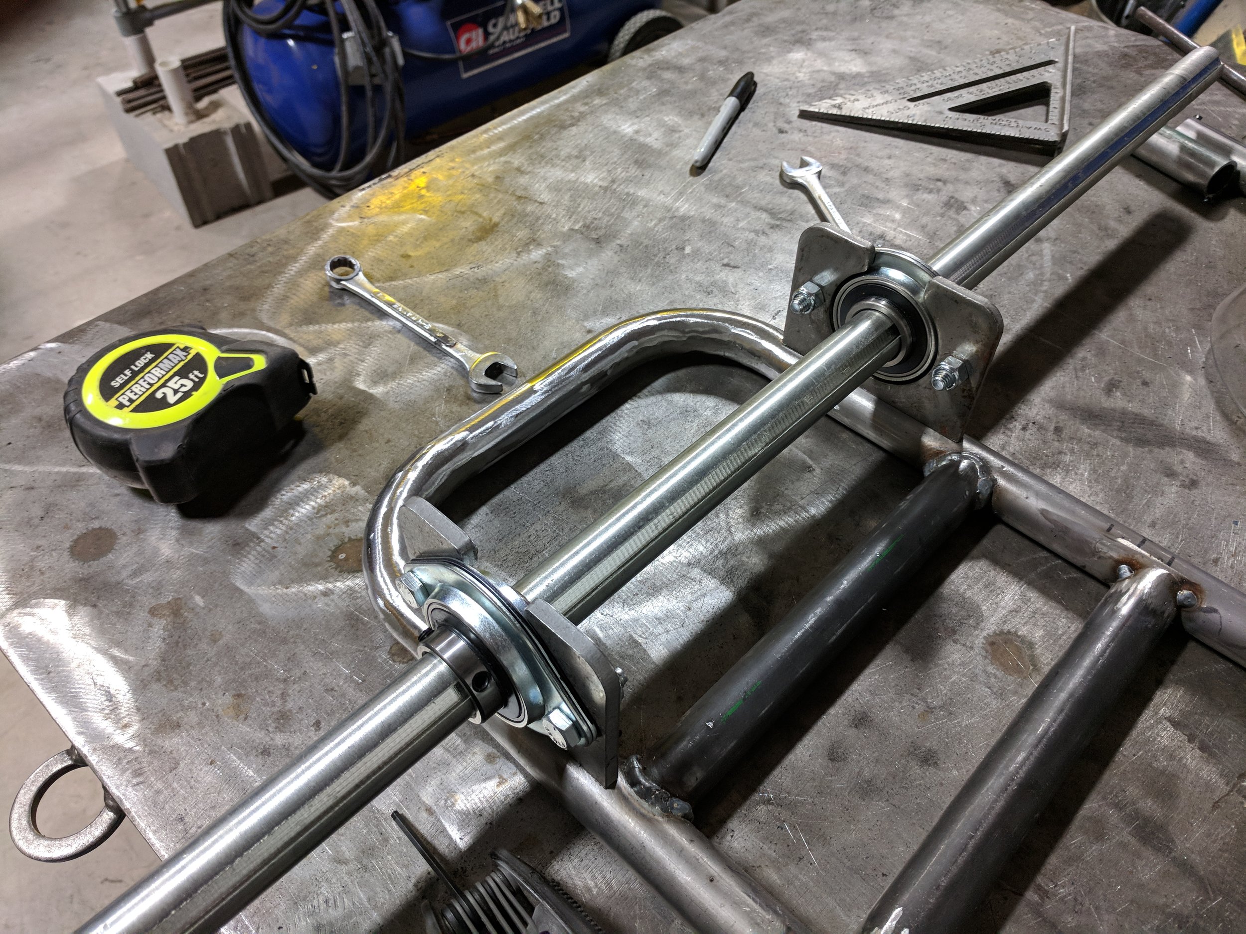
Test fitting the bearing brackets. The bearings brackets were purchased with the bearings. The axle is a 1" steel axle.

Skip some steps and here is the first test fit with the motor. The tape is to prevent metal filings and dust from entering the motor. This is about the spot where I started to stray away from my CAD models. I kept the motor mount edges square for simplicity and added some additional holes and a support bracket.
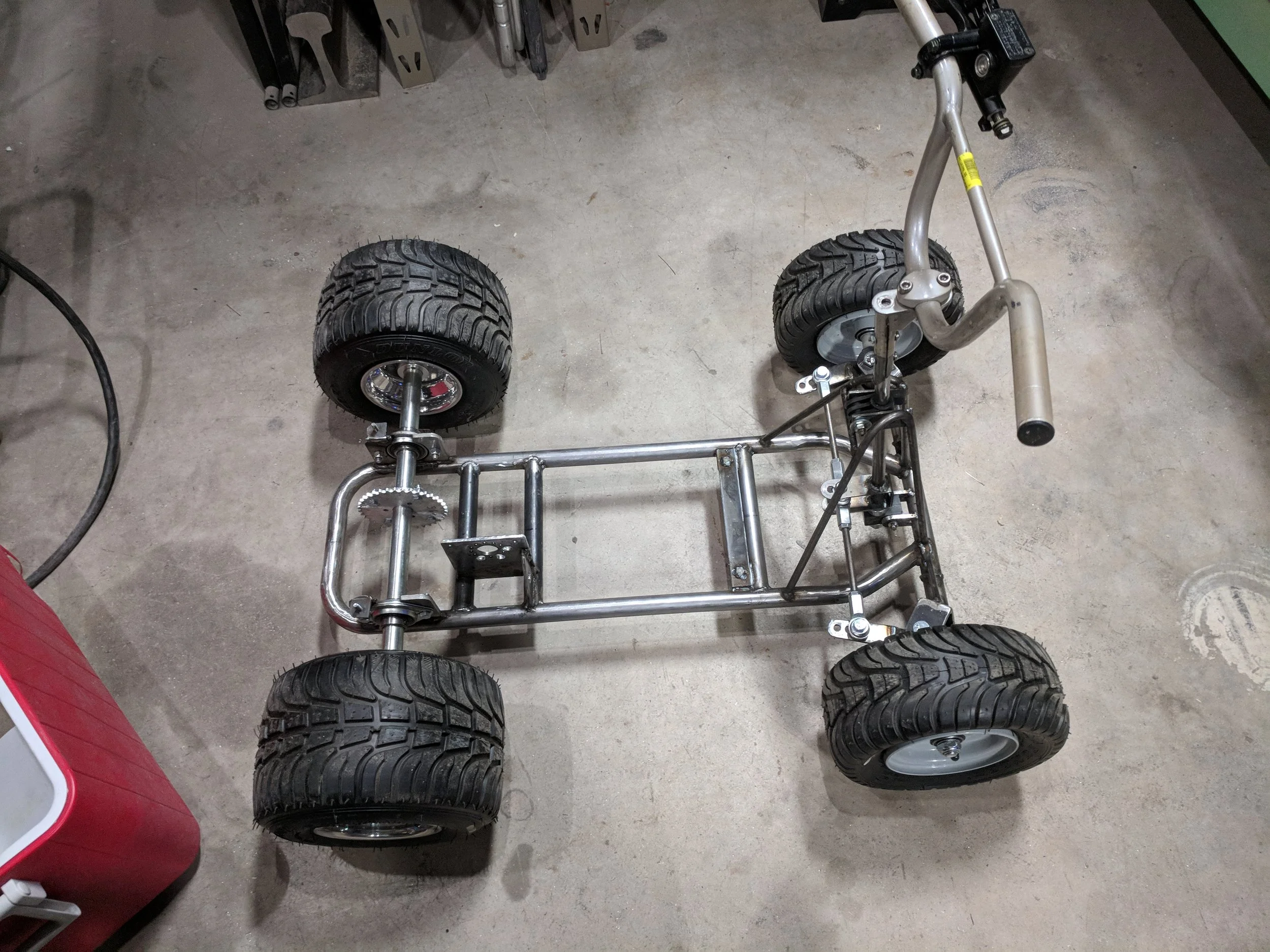
I did some research on steering geometry and thought that replicating a "bar stool racer's" geometry would be best since it's sort of a similar chassis size. The spindle is what the wheel mounts to and the kingpin is the bolt that the spindle pivots on, which is held in a bracket seen in the picture. This bracket is tilted back towards driver when viewed from above which is called positive caster. A couple of degrees of negative camber was also added which means that the top of the wheel tilts in towards the kart body when viewed from the front. This was the first test fit of the spindle brackets. My caster angle ended up being way too extreme (about 12 degrees) so I ended up chopping off the brackets and rewelding them on at about a 5 degree angle. There is about 3 degrees of king pin camber but then the spindle axle was welded on at about a 1-2 degree angle opposing the kingpin angle so the end result is about 1-2 degrees of camber. This geometry is needed to achieve a "jacking effect" on the front wheels where during a turn, the inside wheel is forced into the ground and outside wheel lifted off of the ground. The rider's body weight is then shifted to the front tire that is off of the ground which causes the inside rear tire to lift off the ground slightly. This is needed because this kart uses a solid rear axle (no differential) which does not allow the rear wheels to turn at different speeds. Turning with both rear wheels on the ground is next to impossible. No jigs or templates were used during this whole build which made getting steering geometry difficult to get exactly mirrored but I am happy with the result.
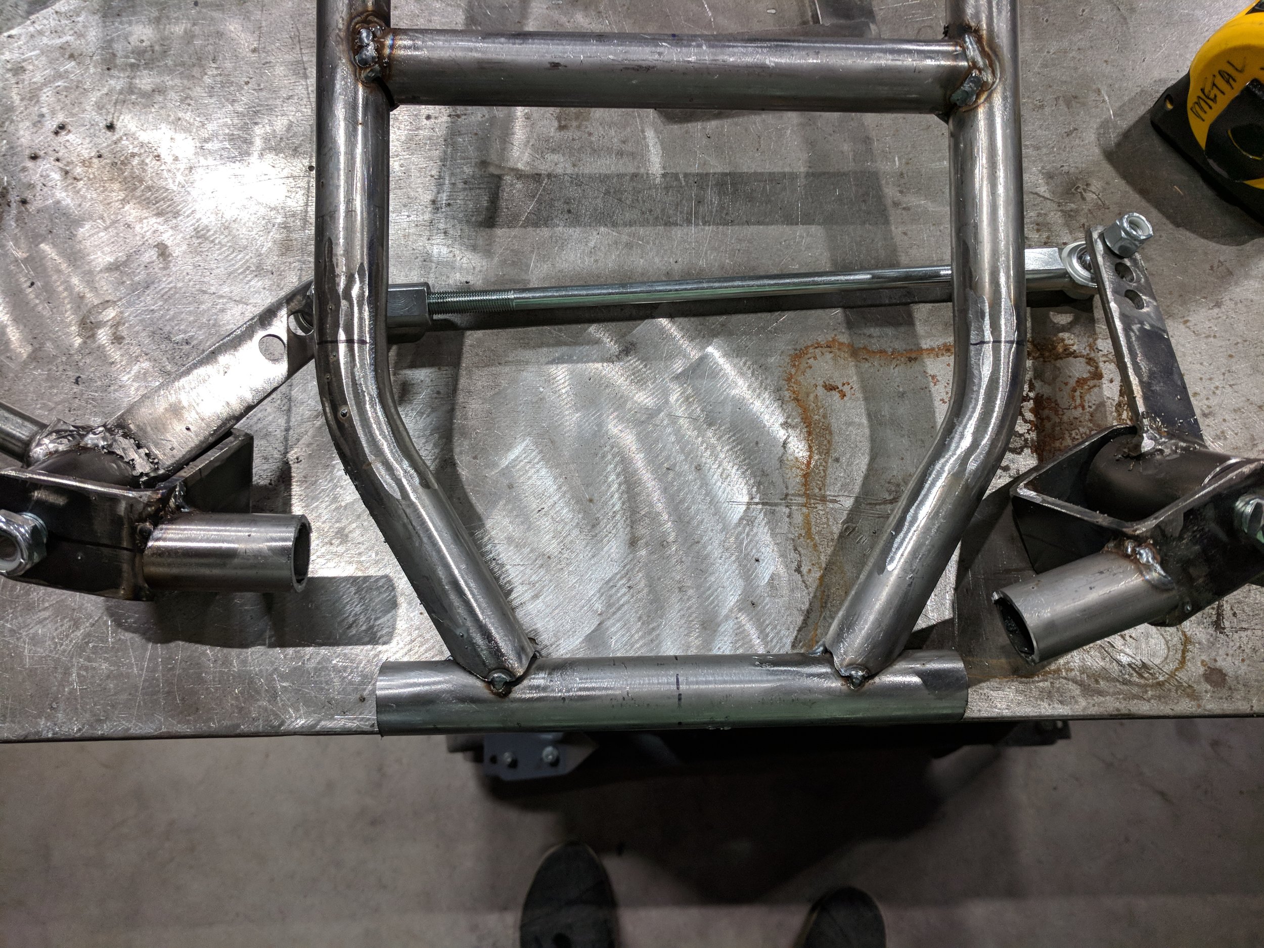
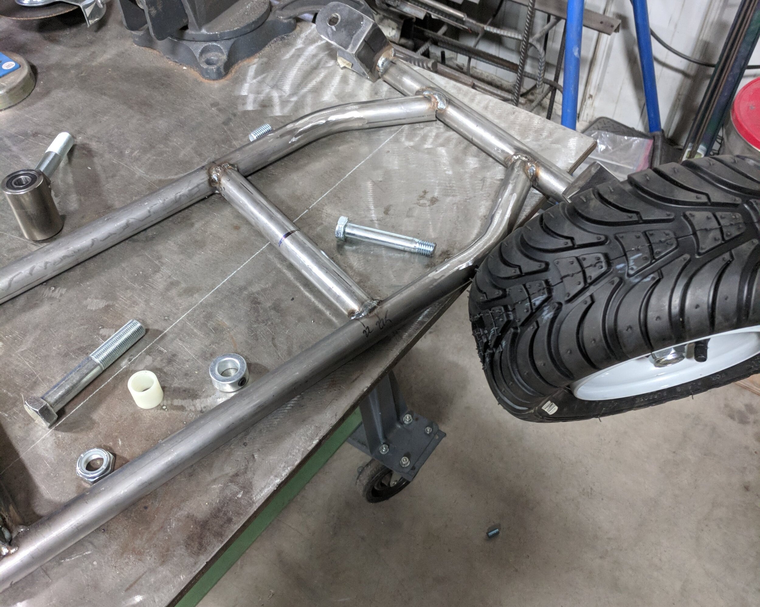
Here are the front spindle brackets after being chopped off. To reweld, I inserted and plugwelded a piece of flat stock vertically through the front tube and into the tubing attached to the brackets to add some rigidity and butt welded the tubing back together.
This is about where I stopped taking pictures consistently. After rewelding the spindle brackets, I built steering column support out of 3/8" round solid steel. I used plastic bushings and locking collars to hold the steer shaft in place. I hope to replace the top bushing with a bearing in the near future for more rigidity. The steering column is a 5/8" steel column with a pitman arm welded to the bottom. The tie rods connect the pitman arm to the spindles.

This is the start of one of the brackets that is used to mount the cooler to the frame.

Further progress on the cooler mounting bracket. The cooler is made out of polyethylene which makes it really really hard to glue. I ended up drilling holes though the exterior shell of the cooler and mounting bracket and using epoxy and 3/4" drywall knotting anchors.

Test fitting the motor and doing it’s first spin up.

Test fitting the cooler.

It’s hard to tell from this angle, but I made a bracket to hold the controller above the motor. This leaves free space above the axel for the batteries. I also added a brake. It’s a single hydraulic moped brake caliper and a tiny 4.5” rotor. Maybe a little undersized, but it can still lock up the tires. Plus the regenerative braking from the motor is able to do most of the braking work.

I added a skeleton to the inside of the cooler to add rigidity and a place to hold the batteries. The skeleton is 1” flat bar stock fastened to the cooler with drywall anchors and epoxy. HDPE is tough to fasten to. The internal skeleton also holds a 150 amp fuse between the battery and controller. at 48volts, that caps max continuous power at 7,200 Watts, or 9.6 HP.

Test fitting it in the car. One of the most important parts was making sure this would fit in my car so it would be easy to transport. Mission accomplished! I don’t even have to fold down the rear seats.
As you can see in this photo, I added a place to put your feet. I changed this later to larger tubing for the foot pegs, added handlebar grips, painted the frame, and that’s about it!